Single cell lithium-ion charger
From ScienceZero
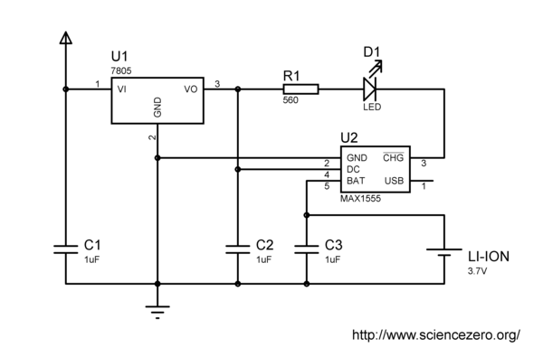
This circuit will deliver up to 300 mA of charge current to a lithium-ion battery/cell from an input voltage of 7 V or higher. The charge controller has built in thermal management and will automatically reduce the charge current if its temperature rises too high. The LED will stay lit until the charge current drops below 50 mA. If U1 is dropped the circuit can work from as low as 4 V and still deliver a useful charge.
The USB pin can be connected to a secondary voltage of up to 6 V, for example a solar panel. The pin is internally current limited to 100 mA. No diode is necessary to prevent the solar panel from discharging the battery in the dark. The charge regulator will automatically switch to the most suitable power source.
 U1 - Any 5 V voltage regulator, will need a heatsink in most cases
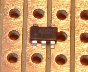
 U2 - Maxim MAX1555 battery charge controller
 C1 - Input capacitor, usually needed for stability
 C2 - Must be within 10 mm of the MAX1555
 C3 - Must be within 10 mm of the MAX1555
 R1 - Current limiter for the LED, stay below 10 mA
 D1 - Any LED that can be lit by 5 V or less

