Difference between revisions of "STM32F407 Microcontroller"
(→Usable Peripherals) |
(→Usable Peripherals) |
||
| Line 4,308: | Line 4,308: | ||
|} | |} | ||
1) garbled characters received<br /> | 1) garbled characters received<br /> | ||
| − | 2) level may be slightly higher then channel 1 with buffer | + | 2) level may be slightly higher then channel 1 with buffer disabled due to external component input pin. Recommended use of buffer. |
=== Used pins === | === Used pins === | ||
Revision as of 12:55, 15 August 2013
Contents
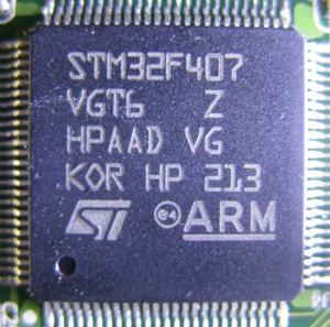
STM32F407VG Microcontroller Overview
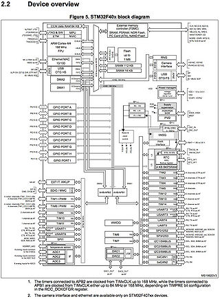
High-performance and DSP with FPU, ARM Cortex-M4 MCU with 1 Mbyte Flash, 192 Kbyte RAM, 168 MHz CPU, Art Accelerator
- 1 Mbyte of 128 bit wide FLASH with 64 cache lines with prefetch for instructions and 8 cache lines for data.
- Ethernet MAC - 10/100 Mbit/s
- USB - 1 x USB OTG FS, 1 x USB OTX HS
- CRC calculation unit - CRC-32 (Ethernet)
- Hash processor - SHA-1, SHA-224, SHA-256, MD5, HMAC
- Cryptographic processor - DES, Triple-DES, AES-128, AES-192, AES-256
- Flexible static memory controller (FSMC) for 8 or 16 bit external memory
- Random number generator - 32 bit every 40 cycles of PLL48CLK
Documents and files
- ARM: Cortex-M3 Thumb-2 instruction set
- Latest version of Keil µVision (Register for free to get the download link)
- STM32F407VG microcontroller datasheet
- ARM Cortex®-M4 Technical Reference Manual
- STM32F40xxx Reference Manual
- Programming manual
- STM32F407VG resources (click the Design Resources tab)
GPIO
The GPIOs (general purpose input/outputs) can sink or source up to ±8 mA, and sink or source up to ±20 mA (with a relaxed VOL/VOH) except PC13, PC14 and PC15 which can sink or source up to ±3mA. When using the PC13 to PC15 GPIOs in output mode, the speed should not exceed 2 MHz with a maximum load of 30 pF.
Memory
Each main block of memory is on a different layer of the bus matrix and can be accessed independently by CPU core or DMA.
FLASH
  Name    Size  Address       Description
  OTP      512        ?       One-time programmable memory for user data

SRAM
  Name    Size  Address       Description
  SRAM1   112KB 0x2000 0000   Main internal SRAM
  SRAM2    16KB 0x2001 C000   Auxiliary internal SRAM
  CCM      64KB 0x1000 0000   Core coupled memory (only accessible by CPU)
  BKPSRAM   4KB 0x4002 4000   Backup SRAM (Battery backup domain)
  FSMC                        Flexible static memory controller (External memory)
Pin functions
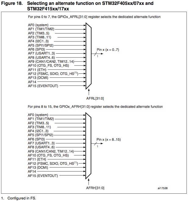
- Functions are not in any particular order. For actual implementation and programming values, see Alternate function mapping
| Pin | Function 1 | Function 2 | Function 3 | Function 4 | Function 5 | Function 6 | Function 7 | Function 8 | Function 9 | Function 10 | Function 11 | Notes |
| PA0 | USART2_CTS | UART4_TX | ETH_MII_CRS | TIM2_CH1_ETR | TIM5_CH1 | TIM8_ETR | EVENTOUT | ADC123_IN0 | WKUP(4) |
| ||
| PA1 | USART2_RTS | UART4_RX | ETH_RMII_REF_CLK | ETH_MII_RX_CLK | TIM5_CH2 | TIM2_CH2 | EVENTOUT | ADC123_IN1 |
| |||
| PA2 | USART2_TX | TIM5_CH3 | TIM9_CH1 | TIM2_CH3 | ETH_MDIO | EVENTOUT | ADC123_IN2 |
| ||||
| PA3 | USART2_RX | TIM5_CH4 | TIM9_CH2 | TIM2_CH4 | OTG_HS_ULPI_D0 | ETH_MII_COL | EVENTOUT | ADC123_IN3 |
| |||
| PA4 | SPI1_NSS | SPI3_NSS | USART2_CK | DCMI_HSYNC | OTG_HS_SOF | I2S3_WS | EVENTOUT | ADC12_IN4 | DAC_OUT1 |
| ||
| PA5 | SPI1_SCK | OTG_HS_ULPI_CK | TIM2_CH1_ETR | TIM8_CH1N | EVENTOUT | ADC12_IN5 | DAC_OUT2 |
| ||||
| PA6 | SPI1_MISO | TIM8_BKIN | TIM13_CH1 | DCMI_PIXCLK | TIM3_CH1 | TIM1_BKIN | EVENTOUT | ADC12_IN6 |
| |||
| PA7 | SPI1_MOSI | TIM8_CH1N | TIM14_CH1 | TIM3_CH2 | ETH_MII_RX_DV | TIM1_CH1N | ETH_RMII_CRS_DV | EVENTOUT | ADC12_IN7 |
| ||
| PA8 | MCO1 | USART1_CK | TIM1_CH1 | I2C3_SCL | OTG_FS_SOF | EVENTOUT |
| |||||
| PA9 | USART1_TX | TIM1_CH2 | I2C3_SMBA | DCMI_D0 | EVENTOUT | OTG_FS_VBUS |
| |||||
| PA10 | USART1_RX | TIM1_CH3 | OTG_FS_ID | DCMI_D1 | EVENTOUT |
| ||||||
| PA11 | USART1_CTS | CAN1_RX | TIM1_CH4 | OTG_FS_DM | EVENTOUT |
| ||||||
| PA12 | USART1_RTS | CAN1_TX | TIM1_ETR | OTG_FS_DP | EVENTOUT |
| ||||||
| PA13 | JTMS-SWDIO | EVENTOUT |
| |||||||||
| PA14 | JTCK-SWCLK | EVENTOUT |
| |||||||||
| PA15 | JTDI | SPI3_NSS | I2S3_WS | TIM2_CH1_ET R | SPI1_NSS | EVENTOUT |
| |||||
| PB0 | TIM3_CH3 | TIM8_CH2N | OTG_HS_ULPI_D1 | ETH_MII_RXD2 | TIM1_CH2N | EVENTOUT | ADC12_IN8 |
| ||||
| PB1 | TIM3_CH4 | TIM8_CH3N | OTG_HS_ULPI_D2 | ETH_MII_RXD3 | TIM1_CH3N | EVENTOUT | ADC12_IN9 |
| ||||
| PB2 | BOOT1 | EVENTOUT |
| |||||||||
| PB3 | JTDO | TRACESWO | SPI3_SCK | I2S3_CK | TIM2_CH2 | SPI1_SCK | EVENTOUT |
| ||||
| PB4 | NJTRST | SPI3_MISO | TIM3_CH1 | SPI1_MISO | I2S3ext_SD | EVENTOUT |
| |||||
| PB5 | I2C1_SMBA | CAN2_RX | OTG_HS_ULPI_D7 | ETH_PPS_OUT | TIM3_CH 2 | SPI1_MOSI | SPI3_MOSI | DCMI_D10 | I2S3_SD | EVENTOUT |
| |
| PB6 | I2C1_SCL | TIM4_CH1 | CAN2_TX | DCMI_D5 | USART1_TX | EVENTOUT |
| |||||
| PB7 | I2C1_SDA | FSMC_NL | DCMI_VSYNC | USART1_RX | TIM4_CH2 | EVENTOUT |
| |||||
| PB8 | TIM4_CH3 | SDIO_D4 | TIM10_CH1 | DCMI_D6 | ETH_MII_TXD3 | I2C1_SCL | CAN1_RX | EVENTOUT |
| |||
| PB9 | SPI2_NSS | I2S2_WS | TIM4_CH4 | TIM11_CH1 | SDIO_D5 | DCMI_D7 | I2C1_SDA | CAN1_TX | EVENTOUT |
| ||
| PB10 | SPI2_SCK | I2S2_CK | I2C2_SCL | USART3_TX | OTG_HS_ULPI_D3 | ETH_MII_RX_ER | TIM2_CH3 | EVENTOUT |
| |||
| PB11 | I2C2_SDA | USART3_RX | OTG_HS_ULPI_D4 | ETH_RMII_TX_EN | ETH_MII_TX_EN | TIM2_CH4 | EVENTOUT |
| ||||
| PB12 | SPI2_NSS | I2S2_WS | I2C2_SMBA | USART3_CK | TIM1_BKIN | CAN2_RX | OTG_HS_ULPI_D5 | ETH_RMII_TXD0 | ETH_MII_TXD0 | OTG_HS_ID | EVENTOUT |
|
| PB13 | SPI2_SCK | I2S2_CK | USART3_CTS | TIM1_CH1N | CAN2_TX | OTG_HS_ULPI_D6 | ETH_RMII_TXD1 | ETH_MII_TXD1 | EVENTOUT | OTG_HS_VBUS |
| |
| PB14 | SPI2_MISO | TIM1_CH2N | TIM12_CH1 | OTG_HS_DM | USART3_RTS | TIM8_CH2N | I2S2ext_SD | EVENTOUT |
| |||
| PB15 | SPI2_MOSI | I2S2_SD | TIM1_CH3N | TIM8_CH3N | TIM12_CH2 | OTG_HS_DP | EVENTOUT | RTC_REFIN |
| |||
| PC0 | OTG_HS_ULPI_STP | EVENTOUT | ADC123_IN10 |
| ||||||||
| PC1 | ETH_MDC | EVENTOUT | ADC123_IN11 |
| ||||||||
| PC2 | SPI2_MISO | OTG_HS_ULPI_DIR | ETH_MII_TXD2 | I2S2ext_SD | EVENTOUT | ADC123_IN12 |
| |||||
| PC3 | SPI2_MOSI | I2S2_SD | OTG_HS_ULPI_NXT | ETH_MII_TX_CLK | EVENTOUT | ADC123_IN13 |
| |||||
| PC4 | ETH_RMII_RX_D0 | ETH_MII_RX_D0 | EVENTOUT | ADC12_IN14 |
| |||||||
| PC5 | ETH_RMII_RX_D1 | ETH_MII_RX_D1 | EVENTOUT | ADC12_IN15 |
| |||||||
| PC6 | I2S2_MCK | TIM8_CH1 | SDIO_D6 | USART6_TX | DCMI_D0 | TIM3_CH1 | EVENTOUT |
| ||||
| PC7 | I2S3_MCK | TIM8_CH2 | SDIO_D7 | USART6_RX | DCMI_D1 | TIM3_CH2 | EVENTOUT |
| ||||
| PC8 | TIM8_CH3 | SDIO_D0 | TIM3_CH3 | USART6_CK | DCMI_D2 | EVENTOUT |
| |||||
| PC9 | I2S_CKIN | MCO2 | TIM8_CH4 | SDIO_D1 | I2C3_SDA | DCMI_D3 | TIM3_CH4 | EVENTOUT |
| |||
| PC10 | SPI3_SCK | I2S3_CK | UART4_TX | SDIO_D2 | DCMI_D8 | USART3_TX | EVENTOUT |
| ||||
| PC11 | UART4_RX | SPI3_MISO | SDIO_D3 | DCMI_D4 | USART3_RX | I2S3ext_SD | EVENTOUT |
| ||||
| PC12 | UART5_TX | SDIO_CK | DCMI_D9 | SPI3_MOSI | I2S3_SD | USART3_CK | EVENTOUT |
| ||||
| PC13 | EVENTOUT | RTC_OUT | RTC_TAMP1 | RTC_TS |
| |||||||
| PC14 | EVENTOUT | OSC32_IN(4) |
| |||||||||
| PC15 | EVENTOUT | OSC32_OUT(4) |
| |||||||||
| PD0 | FSMC_D2 | CAN1_RX | EVENTOUT |
| ||||||||
| PD1 | FSMC_D3 | CAN1_TX | EVENTOUT |
| ||||||||
| PD2 | TIM3_ETR | UART5_RX | SDIO_CMD | DCMI_D11 | EVENTOUT |
| ||||||
| PD3 | FSMC_CLK | USART2_CTS | EVENTOUT |
| ||||||||
| PD4 | FSMC_NOE | USART2_RTS | EVENTOUT |
| ||||||||
| PD5 | FSMC_NWE | USART2_TX | EVENTOUT |
| ||||||||
| PD6 | FSMC_NWAIT | USART2_RX | EVENTOUT |
| ||||||||
| PD7 | USART2_CK | FSMC_NE1 | FSMC_NCE2 | EVENTOUT |
| |||||||
| PD8 | FSMC_D13 | USART3_TX | EVENTOUT |
| ||||||||
| PD9 | FSMC_D14 | USART3_RX | EVENTOUT |
| ||||||||
| PD10 | FSMC_D15 | USART3_CK | EVENTOUT |
| ||||||||
| PD11 | FSMC_CLE | FSMC_A16 | USART3_CT S | EVENTOUT |
| |||||||
| PD12 | FSMC_ALE | FSMC_A17 | TIM4_CH1 | USART3_RTS | EVENTOUT |
| ||||||
| PD13 | FSMC_A18 | TIM4_CH2 | EVENTOUT |
| ||||||||
| PD14 | FSMC_D0 | TIM4_CH3 | EVENTOUT | EVENTOUT |
| |||||||
| PD15 | FSMC_D1 | TIM4_CH4 | EVENTOUT |
| ||||||||
| PE0 | TIM4_ETR | FSMC_NBL0 | DCMI_D2 | EVENTOUT |
| |||||||
| PE1 | FSMC_NBL1 | DCMI_D3 | EVENTOUT |
| ||||||||
| PE2 | TRACECLK | FSMC_A23 | ETH_MII_TXD3 | EVENTOUT |
| |||||||
| PE3 | TRACED0 | FSMC_A19 | EVENTOUT |
| ||||||||
| PE4 | TRACED1 | FSMC_A20 | DCMI_D4 | EVENTOUT |
| |||||||
| PE5 | TRACED2 | FSMC_A21 | TIM9_CH1 | DCMI_D6 | EVENTOUT |
| ||||||
| PE6 | TRACED3 | FSMC_A22 | TIM9_CH2 | DCMI_D7 | EVENTOUT |
| ||||||
| PE7 | FSMC_D4 | TIM1_ETR | EVENTOUT |
| ||||||||
| PE8 | FSMC_D5 | TIM1_CH1N | EVENTOUT |
| ||||||||
| PE9 | FSMC_D6 | TIM1_CH1 | EVENTOUT |
| ||||||||
| PE10 | FSMC_D7 | TIM1_CH2N | EVENTOUT |
| ||||||||
| PE11 | FSMC_D8 | TIM1_CH2 | EVENTOUT |
| ||||||||
| PE12 | FSMC_D9 | TIM1_CH3N | EVENTOUT |
| ||||||||
| PE13 | FSMC_D10 | TIM1_CH3 | EVENTOUT |
| ||||||||
| PE14 | FSMC_D11 | TIM1_CH4 | EVENTOUT |
| ||||||||
| PE15 | FSMC_D12 | TIM1_BKIN | EVENTOUT |
| ||||||||
| PH0 | EVENTOUT | OSC_IN(4) |
| |||||||||
| PH1 | EVENTOUT | OSC_OUT(4) |
|
Alternate function mapping
| Pin | AF 0 | AF 1 | AF 2 | AF 3 | AF 4 | AF 5 | AF 6 | AF 7 | AF 8 | AF 9 | AF 10 | AF 11 | AF 12 | AF 13 | AF 14 | AF 15 |
| SYS | TIM1/2 | TIM3/4/5 | TIM8/9/10/11 | I2C1/2/3 | SPI1/SPI2/I2S2/I2S2ext | SPI3/I2Sext/I2S3 | USART1/2/3/I2S3ext | UART4/5/USART6 | CAN1/CAN2/TIM12/13/14 | OTG_FS/OTG_HS | ETH | FSMC/SDIO/OTG_FS | DCMI | |||
| PA0 | TIM2_CH1_ETR | TIM5_CH1 | TIM8_ETR | USART2_CTS | UART4_TX | ETH_MII_CRS | EVENTOUT | |||||||||
| PA1 | TIM2_CH2 | TIM5_CH2 | USART2_RTS | UART4_RX | ETH_MII_RX_CLK ETH_RMII_REF_CLK |
EVENTOUT | ||||||||||
| PA2 | TIM2_CH3 | TIM5_CH3 | TIM9_CH1 | USART2_TX | ETH_MDIO | EVENTOUT | ||||||||||
| PA3 | TIM2_CH4 | TIM5_CH4 | TIM9_CH2 | USART2_RX | OTG_HS_ULPI_D0 | ETH _MII_COL | EVENTOUT | |||||||||
| PA4 | SPI1_NSS | SPI3_NSS I2S3_WS |
USART2_CK | OTG_HS_SOF | DCMI_HSYNC | EVENTOUT | ||||||||||
| PA5 | TIM2_CH1_ETR | TIM8_CH1N | SPI1_SCK | OTG_HS_ULPI_CK | EVENTOUT | |||||||||||
| PA6 | TIM1_BKIN | TIM3_CH1 | TIM8_BKIN | SPI1_MISO | TIM13_CH1 | DCMI_PIXCK | EVENTOUT | |||||||||
| PA7 | TIM1_CH1N | TIM3_CH2 | TIM8_CH1N | SPI1_MOSI | TIM14_CH1 | ETH_MII_RX_DV ETH_RMII_CRS_DV |
EVENTOUT | |||||||||
| PA8 | MCO1 | TIM1_CH1 | I2C3_SCL | USART1_CK | OTG_FS_SOF | EVENTOUT | ||||||||||
| PA9 | TIM1_CH2 | I2C3_SMBA | USART1_TX | DCMI_D0 | EVENTOUT | |||||||||||
| PA10 | TIM1_CH3 | USART1_RX | OTG_FS_ID | DCMI_D1 | EVENTOUT | |||||||||||
| PA11 | TIM1_CH4 | USART1_CTS | CAN1_RX | OTG_FS_DM | EVENTOUT | |||||||||||
| PA12 | TIM1_ETR | USART1_RTS | CAN1_TX | OTG_FS_DP | EVENTOUT | |||||||||||
| PA13 | JTMS-SWDIO | |||||||||||||||
| PA14 | JTCK-SWCLK | |||||||||||||||
| PA15 | JTDI | TIM2_CH1 TIM2_ETR |
SPI1_NSS | SPI3_NSS I2S3_WS |
||||||||||||
| PB0 | TIM1_CH2N | TIM3_CH3 | TIM8_CH2N | OTG_HS_ULPI_D1 | ETH _MII_RXD2 | EVENTOUT | ||||||||||
| PB1 | TIM1_CH3N | TIM3_CH4 | TIM8_CH3N | OTG_HS_ULPI_D2 | ETH_MII_RXD3 | EVENTOUT | ||||||||||
| PB2 | EVENTOUT | |||||||||||||||
| PB3 | JTDO TRACESWO |
TIM2_CH2 | SPI1_SCK | SPI3_SCK I2S3_CK |
EVENTOUT | |||||||||||
| PB4 | NJTRST | TIM3_CH1 | SPI1_MISO | SPI3_MISO | I2S3ext_SD | EVENTOUT | ||||||||||
| PB5 | TIM3_CH2 | I2C1_SMBA | SPI1_MOSI | SPI3_MOSI I2S3_SD |
CAN2_RX | OTG_HS_ULPI_D7 | ETH_PPS_OUT | DCMI_D10 | EVENTOUT | |||||||
| PB6 | TIM4_CH1 | I2C1_SCL | USART1_TX | CAN2_TX | DCMI_D5 | EVENTOUT | ||||||||||
| PB7 | TIM4_CH2 | I2C1_SDA | USART1_RX | FSMC_NL | DCMI_VSYNC | EVENTOUT | ||||||||||
| PB8 | TIM4_CH3 | TIM10_CH1 | I2C1_SCL | CAN1_RX | ETH _MII_TXD3 | SDIO_D4 | DCMI_D6 | EVENTOUT | ||||||||
| PB9 | TIM4_CH4 | TIM11_CH1 | I2C1_SDA | SPI2_NSS I2S2_WS |
CAN1_TX | SDIO_D5 | DCMI_D7 | EVENTOUT | ||||||||
| PB10 | TIM2_CH3 | I2C2_SCL | SPI2_SCK I2S2_CK |
USART3_TX | OTG_HS_ULPI_D3 | ETH_MII_RX_ER | EVENTOUT | |||||||||
| PB11 | TIM2_CH4 | I2C2_SDA | USART3_RX | OTG_HS_ULPI_D4 | ETH_MII_TX_EN ETH_RMII_TX_EN |
EVENTOUT | ||||||||||
| PB12 | TIM1_BKIN | I2C2_SMBA | SPI2_NSS I2S2_WS |
USART3_CK | CAN2_RX | OTG_HS_ULPI_D5 | ETH_MII_TXD0 ETH_RMII_TXD0 |
OTG_HS_ID | EVENTOUT | |||||||
| PB13 | TIM1_CH1N | SPI2_SCK I2S2_CK |
USART3_CTS | CAN2_TX | OTG_HS_ULPI_D6 | ETH_MII_TXD1 ETH_RMII_TXD1 |
EVENTOUT | |||||||||
| PB14 | TIM1_CH2N | TIM8_CH2N | SPI2_MISO | I2S2ext_SD | USART3_RTS | TIM12_CH1 | OTG_HS_DM | EVENTOUT | ||||||||
| PB15 | RTC_REFIN | TIM1_CH3N | TIM8_CH3N | SPI2_MOSI I2S2_SD |
TIM12_CH2 | OTG_HS_DP | EVENTOUT | |||||||||
| PC0 | ||||||||||||||||
| PC1 | ||||||||||||||||
| PC2 | ||||||||||||||||
| PC3 | ||||||||||||||||
| PC4 | ||||||||||||||||
| PC5 | ||||||||||||||||
| PC6 | ||||||||||||||||
| PC7 | ||||||||||||||||
| PC8 | ||||||||||||||||
| PC9 | ||||||||||||||||
| PC10 | ||||||||||||||||
| PC11 | ||||||||||||||||
| PC12 | ||||||||||||||||
| PC13 | ||||||||||||||||
| PC14 | ||||||||||||||||
| PC15 | ||||||||||||||||
| PD0 | ||||||||||||||||
| PD1 | ||||||||||||||||
| PD2 | ||||||||||||||||
| PD3 | ||||||||||||||||
| PD4 | ||||||||||||||||
| PD5 | ||||||||||||||||
| PD6 | ||||||||||||||||
| PD7 | ||||||||||||||||
| PD8 | ||||||||||||||||
| PD9 | ||||||||||||||||
| PD10 | ||||||||||||||||
| PD11 | ||||||||||||||||
| PD12 | ||||||||||||||||
| PD13 | ||||||||||||||||
| PD14 | ||||||||||||||||
| PD15 | ||||||||||||||||
| PE0 | ||||||||||||||||
| PE1 | ||||||||||||||||
| PE2 | ||||||||||||||||
| PE3 | ||||||||||||||||
| PE4 | ||||||||||||||||
| PE5 | ||||||||||||||||
| PE6 | ||||||||||||||||
| PE7 | ||||||||||||||||
| PE8 | ||||||||||||||||
| PE9 | ||||||||||||||||
| PE10 | ||||||||||||||||
| PE11 | ||||||||||||||||
| PE12 | ||||||||||||||||
| PE13 | ||||||||||||||||
| PE14 | ||||||||||||||||
| PE15 | ||||||||||||||||
| PF0 | ||||||||||||||||
| PF1 | ||||||||||||||||
| PF2 | ||||||||||||||||
| PF3 | ||||||||||||||||
| PF4 | ||||||||||||||||
| PF5 | ||||||||||||||||
| PF6 | ||||||||||||||||
| PF7 | ||||||||||||||||
| PF8 | ||||||||||||||||
| PF9 | ||||||||||||||||
| PF10 | ||||||||||||||||
| PF11 | ||||||||||||||||
| PF12 | ||||||||||||||||
| PF13 | ||||||||||||||||
| PF14 | ||||||||||||||||
| PF15 | ||||||||||||||||
| PG0 | ||||||||||||||||
| PG1 | ||||||||||||||||
| PG2 | ||||||||||||||||
| PG3 | ||||||||||||||||
| PG4 | ||||||||||||||||
| PG5 | ||||||||||||||||
| PG6 | ||||||||||||||||
| PG7 | ||||||||||||||||
| PG8 | ||||||||||||||||
| PG9 | ||||||||||||||||
| PG10 | ||||||||||||||||
| PG11 | ||||||||||||||||
| PG12 | ||||||||||||||||
| PG13 | ||||||||||||||||
| PG14 | ||||||||||||||||
| PG15 | ||||||||||||||||
| PH0 | ||||||||||||||||
| PH1 | ||||||||||||||||
| PH2 | ||||||||||||||||
| PH3 | ||||||||||||||||
| PH4 | ||||||||||||||||
| PH5 | ||||||||||||||||
| PH6 | ||||||||||||||||
| PH7 | ||||||||||||||||
| PH8 | ||||||||||||||||
| PH9 | ||||||||||||||||
| PH10 | ||||||||||||||||
| PH11 | ||||||||||||||||
| PH12 | ||||||||||||||||
| PH13 | ||||||||||||||||
| PH14 | ||||||||||||||||
| PH15 | ||||||||||||||||
| PI0 | ||||||||||||||||
| PI1 | ||||||||||||||||
| PI2 | ||||||||||||||||
| PI3 | ||||||||||||||||
| PI4 | ||||||||||||||||
| PI5 | ||||||||||||||||
| PI6 | ||||||||||||||||
| PI7 | ||||||||||||||||
| PI8 | ||||||||||||||||
| PI9 | ||||||||||||||||
| PI10 | ||||||||||||||||
| PI11 | ||||||||||||||||
| PI12 | ||||||||||||||||
| PI13 | ||||||||||||||||
| PI14 | ||||||||||||||||
| PI15 |
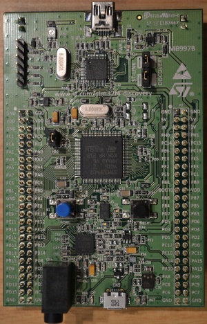
STM32F4DISCOVERY Development Board Overview
- (STM32F407VGT6 microcontroller featuring 32-bit ARM Cortex-M4F core, 1 MB Flash, 192 KB RAM in an LQFP100 package
- On-board ST-LINK/V2 with selection mode switch to use the kit as a standalone ST- LINK/V2 (with SWD (Serial Wire Debug) connector for programming and debugging)
- Board power supply: through USB bus or from an external 5 V supply voltage
- External application power supply: 3 V and 5 V
- LIS302DL, ST MEMS motion sensor, 3-axis digital output accelerometer
- MP45DT02, ST MEMS audio sensor, omni-directional digital microphone
- CS43L22, audio DAC with integrated class D speaker driver
- Eight LEDs:
- LD1 (red/green) for USB communication
- LD2 (red) for 3.3 V power on
- Four user LEDs
- LD3 (orange)
- LD4 (green)
- LD5 (red)
- LD6 (blue)
- 2 USB OTG LEDs
- LD7 (green) VBus
- LD8 (red) over-current
- Two push buttons
- user
- reset
- USB OTG FS with micro-AB connector
- Extension header for all LQFP100 I/Os for quick connection to prototyping board and easy probing
Documents and files
- Discovery kit for STM32 F4 series - with STM32F407VG MCU
- STM32F4 high-performance discovery board
- Schematic
- User manual - getting started
- User manual
- Programming manual
- Example code
- About example code
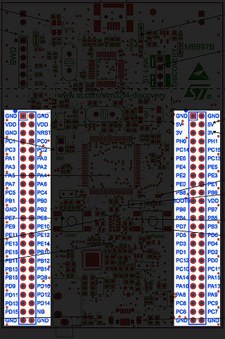
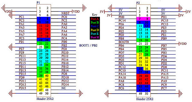
Pinout
Available pins on board
| Bit | 0 | 1 | 2 | 3 | 4 | 5 | 6 | 7 | 8 | 9 | 10 | 11 | 12 | 113 | 14 | 15 |
| Port A | PA0 | PA1 | PA2 | PA3 | PA4 | PA5 | PA6 | PA7 | PA8 | PA9 | PA10 | PA13 | PA14 | PA15 | ||
| Port B | PB0 | PB1 | PB2 | PB3 | PB4 | PB5 | PB6 | PB7 | PB8 | PB9 | PB10 | PB11 | PB12 | PB13 | PB14 | PB15 |
| Port C | PC0 | PC1 | PC2 | PC3 | PC4 | PC5 | PC6 | PC7 | PC8 | PC9 | PC10 | PC11 | PC12 | PC13 | PC14 | PC15 |
| Port D | PD0 | PD1 | PD2 | PD3 | PD4 | PD5 | PD6 | PD7 | PD8 | PD9 | PD10 | PD11 | PD12 | PD13 | PD14 | PD15 |
| Port E | PE0 | PE1 | PE2 | PE3 | PE4 | PE5 | PE6 | PE7 | PE8 | PE9 | PE10 | PE11 | PE12 | PE13 | PE14 | PE15 |
| Port F | ||||||||||||||||
| Port G | ||||||||||||||||
| Port H | PH0 | PH1 | ||||||||||||||
| Port I |
Usable Peripherals
Note: this is an incomplete list, based on ongoing development and testing
| Peripheral | Function | Pin |
| USART1 | TX | PA9 (1) |
| USART1 | RX | PA10 |
| USART2 | TX | PA2 |
| USART2 | RX | PA3 |
| USART3 | TX | PB10 |
| USART3 | RX | PB11 |
| UART4 | TX | PA0 |
| UART4 | RX | PA1 |
| UART5 | TX | PC12 |
| UART5 | RX | PD2 |
| USART6 | TX | PC6 |
| USART6 | RX | PC7 |
| DAC | OUT1 | PA4 |
| DAC | OUT2 | PA5 (2) |
1) garbled characters received
2) level may be slightly higher then channel 1 with buffer disabled due to external component input pin. Recommended use of buffer.
Used pins
| Pin | Direction | Connected to |
| PA1 | ← weak |
|
| PA4 |
| |
| PA5 | → |
|
| PA7 |
| |
| PA8 |
| |
| PA9 | ↔ strong (1) |
|
| PA10 |
| |
| PA11 | ↔ strong (3) |
|
| PA12 | ↔ strong (3) |
|
| PB2 | ← weak |
|
| PB6 |
| |
| PB6 | ← weak |
|
| PB9 |
| |
| PB9 | ← weak |
|
| PB10 | → |
|
| PB12 | ↔ strong (2) |
|
| PB14 | ↔ strong (2) |
|
| PC0 | → |
|
| PC3 | ← strong |
|
| PC7 | → |
|
| PC10 | → |
|
| PC12 | → |
|
| PC13 | ← weak |
|
| PD4 | → |
|
| PD5 | ← strong |
|
| PD12 | → |
|
| PD13 | → |
|
| PD14 | → |
|
| PD15 | → |
|
| PE0 |
| |
| PE1 |
| |
| PE3 |
| |
| PE6 |
| |
| PH0 | ← |
|
| PH1 | → |
|
Notes
- 1. Depends if a USB micro is plugged in, and to what
- 2. Depends if connected IO is in input mode
- 3. Not broken out to pins
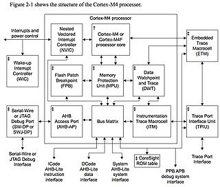
CPU core
Programming
IMPORTANT: If using Keil µVision with hardware FPU selected in the project options, please be sure to enable the FPU before any floating point numbers are loaded or processed.
This can be done by setting bits 20 to 23 in CPACR (address 0xE000ED88)
If using C, this can be done by:
#define CPACR   						(*((volatile unsigned long *) 0xE000ED88))
CPACR |= 0xFu<<20;
