Difference between revisions of "PIC programmer: High voltage"
From ScienceZero
(→Programming Software) |
|||
| Line 10: | Line 10: | ||
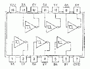
[[image:74hct14.gif|right|thumb|74HCT14]] | [[image:74hct14.gif|right|thumb|74HCT14]] | ||
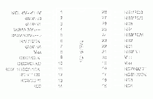
[[image:16f870.gif|right|thumb|PIC 16F870]] | [[image:16f870.gif|right|thumb|PIC 16F870]] | ||
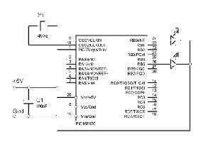
| + | [[image:16F870test.gif|thumb|left|Test circuit]] | ||
High-voltage parallel port programmer | High-voltage parallel port programmer | ||
| Line 49: | Line 50: | ||
<br> | <br> | ||
| − | Load the test program [http://www.sciencezero.org/download/electronics/16F870.HEX "16F870.HEX"] | + | #Load the test program [http://www.sciencezero.org/download/electronics/16F870.HEX "16F870.HEX"] |
| − | Set "Config" to 3F71 | + | #Set "Config" to 3F71 |
| − | Click "Program" | + | #Click "Program" |
| − | + | #A LED between GND and RB0-RB7 will show flashing at different frequencies | |
| − | A LED between GND and RB0-RB7 will show flashing at different frequencies | + | |
| − | + | ||
The source code is here: [http://www.sciencezero.org/download/electronics/16F870.asm "16F870.asm"] | The source code is here: [http://www.sciencezero.org/download/electronics/16F870.asm "16F870.asm"] | ||
Revision as of 23:01, 1 February 2007
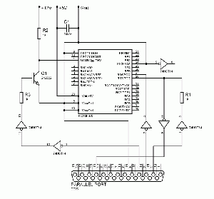
High-voltage parallel port programmer
This programmer works on Flash based PIC microcontrollers. It is based on a design by David Tait but uses schmitt triggers as buffers for improved stability.
- 16F628
- 16F870 - tested
- 16F873
- 16F874
- 16F876
- 16F877
The parallel cable should be as short as possible, it did work on a 1.5 metre extension cable but should be tested with a short cable
Programming Software
David Tait's Flash PIC Programmer (FPP)
Mirror: - fpp09.zip (183 KB)
Click "Setup" and change to these settings.
It is important that you remember to click "Apply".
Click "Define/Test" and change to these settings.
It is important that you remember to click "Apply".
- Load the test program "16F870.HEX"
- Set "Config" to 3F71
- Click "Program"
- A LED between GND and RB0-RB7 will show flashing at different frequencies
The source code is here: "16F870.asm"


