The Speed Trap version 1.00b
When designing this circuit the goal was to use as few parts as possible so everyone can afford and manage to build it. The prototype was built using a PIC 16C84, but the 16F84 and 16F84A should work just as well.
Configure the display
Hold down Button 3 and turn on the power. Hold the button until
the display shows [123]. The chip is now configured for the correct display type and will
flash the version number [100] and show the ready sign [rdy].
Select a unit of measurement
It is up to the user to decide on the unit of measurement. The speed is
reported in the same unit as the light gate measurements were done in. If you don't have a
very good reason for using something else I suggest you use meter as the base unit. If you
prefer the triggers to be spaced less than one unit apart, then use Button 4 to select a
suitable fraction.
Triggers
The trigger pulse needs to last 10µS or more to be sure that it will always be
registered. Pulses down to 1µS can be used if 100% success rate is not required.
RA3 needs to be triggered first and will start the timer, after the pulse is registered
RA3 it is free to change logic level. RA4 requires the same pulse width and stops the
timer when triggered. The triggers can be photodiodes, switches or any detector capable of
emitting TTL compatible voltage levels. Button 5 chooses between trigger on logic 1
and trigger on logic 0. RA3 and RA4 are CMOS inputs with TTL compatible voltage levels.
Power
The circuit will work at voltages from 2-6V, remember that the voltages on the trigger
inputs should not exceed the supply voltage. C3 should be placed as close as possible to
the chip, if omitted it may cause the chip to crash or behave erratically. The displays
will be very dim when run on low voltages. Average supply current is 10-60mA depending on
the type of displays and the supply voltage.
Buttons
All buttons except Button 1 are optional, you only need to add buttons for the functions
that you want to use. Debouncing is done in software and most Normally Open buttons should
work fine.
Oscillator (4 MHz)
A crystal is the most accurate and expensive option. A ceramic resonator is
cheaper but can give errors of about 0.5%. The capacitors C1 and C2 are optional and will
give slightly higher stability when present. The triggers will likely be the largest
source of error even when a ceramic resonator is used.
Accuracy
The accuracy in testing was better than 1 m/s double checked by a digital
oscilloscope. To test the circuit and your settings, place the trigger switches vertically
and time an object in free fall. The average acceleration of gravity on earth is
9.81m/s^2. The time for an object to fall from a height h to the ground is t = sqrt( 2 * h
/ 9.81 ). So if you place the triggers one meter apart vertically it will take exactly t =
sqrt( 2 / 9.81) = 0.452 seconds for the object to fall from one trigger to the next. If
you use an object that is relatively heavy for it's size and start it just above the first
trigger you should get a time that is very close to theory. With the prototype it was
possible to get within two ms even with a handheld first trigger.
Operation of the Speed Trap
| Word | Definition |
| Unit | The unit (meter, foot) you measured the light gate spacing in |
| µS | Time in Microseconds, 1/1 000 000 |
| mS | Time in Miliseconds, 1/1000 |
| Unit/s | Speed in Unit per second |
| Kilo Unit/h | Speed in (Unit*1000) per hour |
| Normal Operation | |||
| Button | Name | Action | Display |
| 1 | Arm | Enter timer mode | [= =], [Err] (Check inputs) |
| 2 | Previous | Cycle the 16 latest recorded values | [000], [-E-] (Overflow) |
| 3 | Type | Select µs, ms, Unit/s or Kilo Unit/h | [ uS], [nnS], [U/S], [U/H] |
| 4 | Length | Select 10, 20 ... 100% of one Unit | [L01] ... [L10] |
| 5 | Trigger | Select trigger on logic level 0 or 1 | [--|_], [__|-] |
| 6 | Debug | Display the RA3 and RA4 Trigger inputs | [0-0] |
| During Startup | |||
| Button | Name | Action | Display |
| 1 | Arm | Set default state | [CLr] |
| 2 | Previous | Clear recorded values | [C16] |
| 3 | Type | Select display Type | [123] |
| Default settings | |
Name |
Value |
| Previous | 000 |
| Type | U/S |
| Length | L03 |
Trigger |
[__|-] |
Speed Trap Hardware
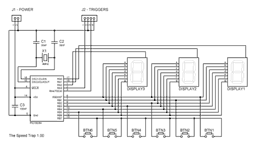
Shematics (display 3 is the most significant digit):

| PORTA - Pin direction and assignment | |||
| Name | Pin | Direction | Function |
| RA0 | 17 | Out | Select display 1 |
| RA1 | 18 | Out | Select display 2 |
| RA2 | 1 | Out | Select display 3 |
| RA3 | 2 | In | Trigger input 1 |
| RA4 | 3 | In | Trigger input 2 |
| PORTB - Pin direction and assignment | |||
| Name | Pin | Direction | Function |
| RB0 | 6 | Out | Display segment a |
| RB1 | 7 | Out | Display segment b |
| RB2 | 8 | Out | Display segment c |
| RB3 | 9 | Out | Display segment d |
| RB4 | 10 | Out | Display segment e |
| RB5 | 11 | Out | Display segment f |
| RB6 | 12 | Out | Display segment g |
| RB7 | 13 | In | Button multiplexer (RB0-RB6) |
Segments |
|||||
| a | a | a | a | ||
| f | b | ||||
| f | b | ||||
| g | g | g | g | ||
| e | c | ||||
| e | c | ||||
| d | d | d | d | ||
Programming the PIC
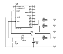
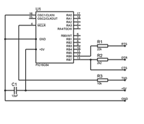
COM84 style PIC programmer:


Some serialports have problems supplying enough current for stable operation, it
may help to increase the value of C1. Another solution is to use an external regulated 5V
PSU.
| Configuration bits | ||
Name |
16C84 | 16F84 |
| _CP_OFF | H'3FFF' | H'3FFF' |
| _WDT_OFF | H'3FFB' | H'3FFB' |
| _XT_OSC | H'3FFD' | H'3FFD' |
_PWRTE_ON |
H'3FFF' | H'3FF7' |
Serialport Pin Assignment |
||
| Name | DB-9 | DB-25 |
| TXD | Pin 3 | Pin 2 |
| DTR | Pin 4 | Pin 20 |
| GND | Pin 5 | Pin 7 |
| RTS | Pin 7 | Pin 4 |
| CTS | Pin 8 | Pin 5 |
Reccommended software is WinPic: http://www.qsl.net/dl4yhf/winpicpr.html
Notes:
Where:
m = Mass in Kilogram
v = Velocity in m/s
e = Energy in Joule (watt second)
Example:
m = 10 gram (0.01 kg)
v = 35 m/s
e = 0.5 * 0.01 * (35 * 35)
e = 6.125 Joule